This is an old revision of the document!
Table of Contents
QRSS MEPT
I started work on my small QRSS MEPT idea with a simple Arduino / SI5351 / 16×2 LCD arrangement. The LCD is only there because I found this breadboard setup already with Seeeduino Nano, SI5351 and LCD in my box of “Arduino Project bits” - from a previous experiment - and I thought I'd keep it for the time being as a display to help in debugging (?). Once the MEPT is functional and ready for operation I'll remove the LCD (and its code from the sketch)
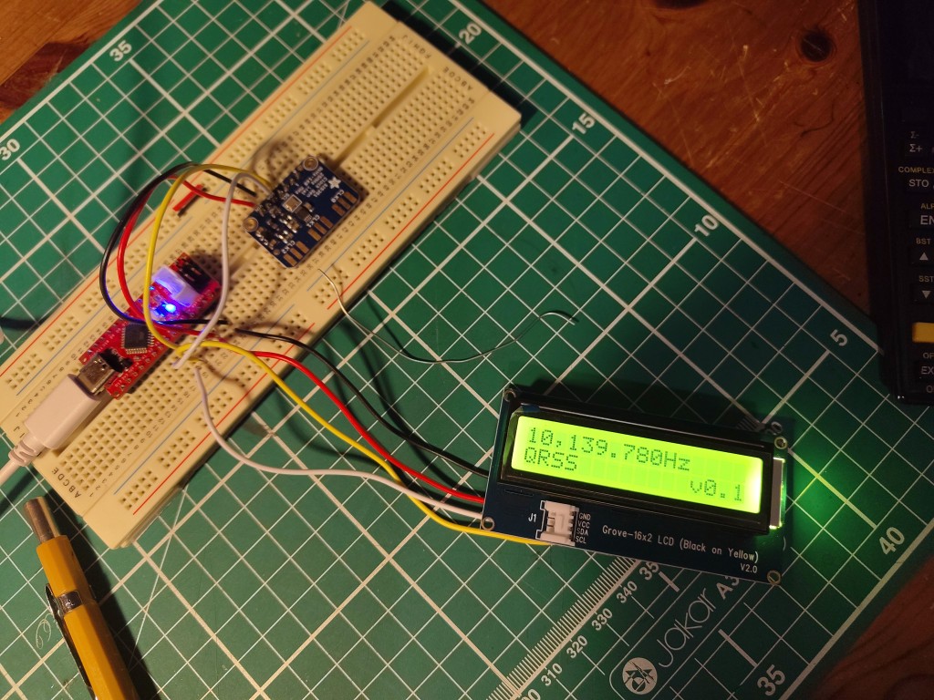
Step one
- modify an old sketch & strip out un-needed code until I had a simple carrier generator
- add function to vary the frequency in a stepped-ramp sequence to check operation
- add functions to make dits and dahs and spaces of appropriate lengths
- add function to send a callsign/message explicitly entered as a series of calls to
dah(),dit()andspace()and run it fromloop() - add code to light an onboard LED during “key-down”
- add code to show operating frequency and the letters of the callsign as they're sent on the LCD
I monitored the SI5351 output on my normal 30m grabber - there's enough radiation direct from the SI5351 board to make a trace on the waterfall.

The sketch
#include <rgb_lcd.h>
#include <si5351.h>

char version[] = "v0.1";


volatile long shift_hz = 0;
int count = 0;
int dit_time = 6000;

volatile long freq = 10139780;  //

int digit0 = 0;
int digit1 = 0;
int digit2 = 0;
int digit3 = 0;
int digit4 = 0;
int digit5 = 0;
int digit6 = 0;
int digit7 = 0;


// Instantiate the Objects
rgb_lcd lcd;
Si5351 si5351;

void setup()
{

  // Initialize the display
  lcd.begin(16, 2);

  lcd.cursor();

  // Initialize the Si5351
  si5351.init(SI5351_CRYSTAL_LOAD_8PF, 0, 0);
  si5351.set_correction(-37500, SI5351_PLL_INPUT_XO);
  si5351.set_pll(SI5351_PLL_FIXED, SI5351_PLLA);
  si5351.drive_strength(SI5351_CLK0, SI5351_DRIVE_8MA);

  pinMode(13, OUTPUT);
  // Update display and send start frequency

    SendFrequency();
    digit0 = (freq%10);
    digit1 = ((freq/10)%10);
    digit2 = ((freq/100)%10);
    digit3 = ((freq/1000)%10);
    digit4 = ((freq/10000)%10);
    digit5 = ((freq/100000)%10);
    digit6 = ((freq/1000000)%10);
    digit7 = ((freq/10000000)%10);

    UpdateDisplay();

}


void loop()
{

// SendRamp();
SendCall();
// SendRamp();

}


void SendCall() {

  space();

  dah();
  dah();
  dit();
  lcd.setCursor(5,1);
  lcd.print("G");
  space();


  dah();
  dah();
  lcd.setCursor(6,1);
  lcd.print("M");
  space();


  dit();
  dit();
  dit();
  dit();
  dah();
  lcd.setCursor(7,1);
  lcd.print("4");
  space();

  dit();
  dit();
  dit();
  lcd.setCursor(8,1);
  lcd.print("S");
  space();

  dit();
  dah();
  dit();
  dit();
  lcd.setCursor(9,1);
  lcd.print("L");
  space();

  dit();
  dit();
  dit();
  dah();
  lcd.setCursor(10,1);
  lcd.print("V");
  space();

  space();


}


void space() {
  shift_hz = 0;
  SendFrequency();
  delay(dit_time * 2);
}

void dah() {
  shift_hz = 4;
  digitalWrite(13, HIGH);
  SendFrequency();
  delay(dit_time * 3);
  shift_hz = 0;
  SendFrequency();
  digitalWrite(13, LOW);
  delay(dit_time);

}

void dit() {
  shift_hz = 4;
  digitalWrite(13, HIGH);
  SendFrequency();
  delay(dit_time);
  shift_hz = 0;
  SendFrequency();
  digitalWrite(13, LOW);
  delay(dit_time);

}

void SendRamp() {

 shift_hz = 0;
 while ( shift_hz < 6 ) {
  digitalWrite(13, HIGH);
 SendFrequency();
   shift_hz++;
   delay(2000);
   SendFrequency();
 }
   shift_hz = 0;
   SendFrequency();
   delay (dit_time * 2);

   digitalWrite(13, LOW);
}

void UpdateDisplay()
{


  lcd.setCursor(0,0);
  lcd.print(digit7);
  lcd.setCursor(1,0);
  lcd.print(digit6);
  lcd.setCursor(2,0);
  lcd.print(",");
  lcd.setCursor(3,0);
  lcd.print(digit5);
  lcd.setCursor(4,0);
  lcd.print(digit4);
  lcd.setCursor(5,0);
  lcd.print(digit3);
  lcd.setCursor(6,0);
  lcd.print(".");
  lcd.setCursor(7,0);
  lcd.print(digit2);
  lcd.setCursor(8,0);
  lcd.print(digit1);
  lcd.setCursor(9,0);
  lcd.print(digit0);
  lcd.setCursor(10,0);
  lcd.print("Hz");

  lcd.setCursor(0,1);

  lcd.print("QRSS");

  lcd.setCursor(12,1);
  lcd.print(version);

}

void SendFrequency()
{

  si5351.set_freq(((freq + shift_hz) * 100ULL), SI5351_CLK0);     // VFO

}
Step Two
The next step will be to build a small TX PA to boost the SI5351 output up to around 1W and a LPF. I'll add a PTT line to key the PA, driven from the Arduino so that the sketch can have periods of carrier off between cycles if necessary. 1W should be enough power and should be simple enough to generate. I might have a go at a Class-E MOSFET amplifier.

Further Information
Page created : 12/07/26 07:40 BST
Page updated : 12/07/26 08:08 BST


Discussion